Designing and Manufacturing a Motor Replacement Dummy Shaft in the Nick of Time!

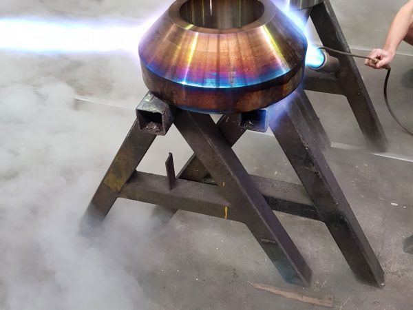
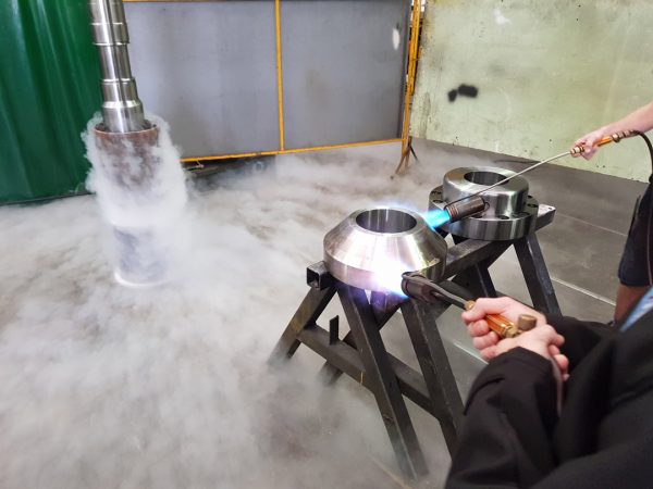
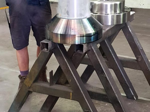
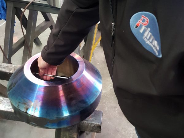
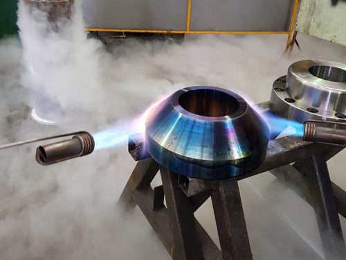
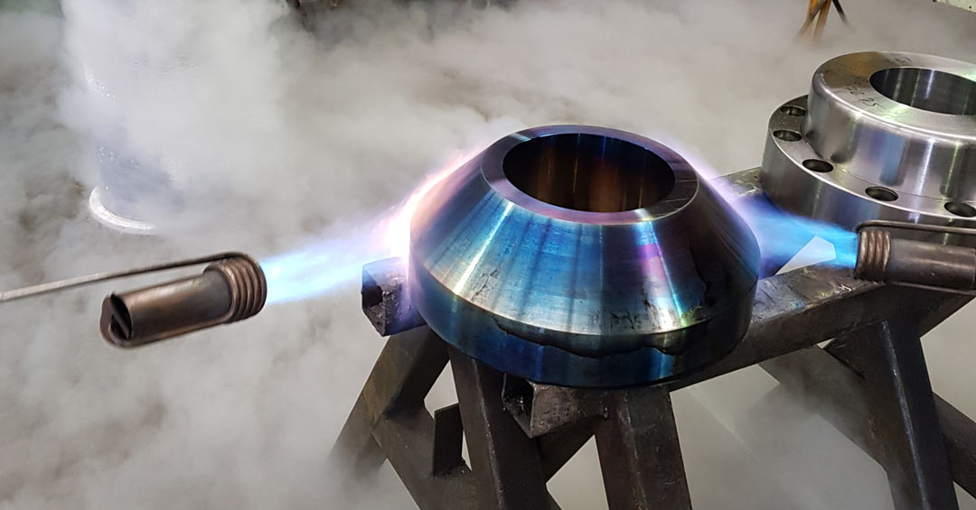
Heating flange with blow torch

OUR EXPERIENCE
Designing and Manufacturing a Motor Replacement Dummy Shaft in the Nick of Time!

Prime was called upon to design and manufacture a motor replacement dummy shaft in a very strict time frame. We set out to achieve the challenge of working quickly, yet thoroughly.

The Challenge:

Our client was in charge of servicing a series of electric motors that were mounted inline. The catch was that they could only service each motor individually in turn. They had to keep the rest of the motors running, as the entire line could not be shut down for the time it would take to service just one. This would be far too costly, with a drastic loss in revenue for their customer. The only option was to fashion a replacement motor shaft to stand in for the one that needed to be removed and serviced.

So in light of these requirements, our client contacted us to design and create a dummy shaft that would be a replacement for the motor. This way, the rest of the motors connected inline could continue running as usual while our client serviced the problem motor externally.

The main challenge in this job was the fact that no drawings were available of the original rotor shaft. This meant that we had to wait until the motor that needed servicing was removed so that we could measure it. We had to manufacture the dummy replacement shaft in the shortest time possible to reduce our client’s customers’ downtime.

So we got to work quick smart!

What we did:

1

We measured the rotor shaft to begin designing and making technical drawings of the dummy shaft.

2

The flanges on the ends of the shaft had to be friction drive couplings (no keys or splines). This meant the couplings had a interference fit to the shaft to create enough friction not to spin on the shaft under load.

3

We selected the correct material that would be able to handle the torque loads.

4

It was then critical that we used the Young’s modulus value and Poisson ratio of the material being used.

5

Part of the interference calculations required a certain surface finish of the mating journals and the engagement length.

6

Calculations were then done to work out the diameter differences needed of the shaft to the coupling bore (interference). We wanted to ensure that the correct pressure was generated between the shaft and the coupling to end up with the right figure of force.

7

We then assessed the coefficient expansion rate of the materials to decide how much heat was needed to expand the coupling. Because it is made of high tensile steel, however, we could only heat it to a certain temperature. Going over that temperature would mean that the material would anneal and would then loose tensile and yield strength.

8

Unfortunately, with the amount of interference needed, we found that heating the coupling up to its maximum allowed temperature was not enough thermal expansion to create clearance to the shaft to be able to fit it. So we had to take another step to achieve enough clearance to drop the shaft in.

9

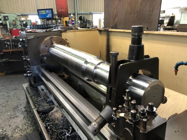
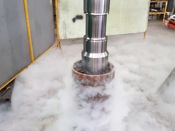
The only option was to freeze the shaft with liquid nitrogen (-195.79 °C) in order to shrink it. We then heated the coupling to expand it, and with both of these methods combined, managed to slot the shaft into the coupling. Once the shaft and coupling both reached ambient temperature, the pressure generated between created the right amount of friction to perform the task.

10

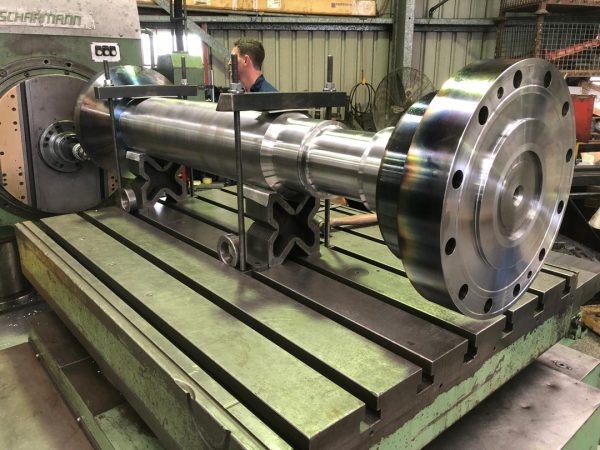
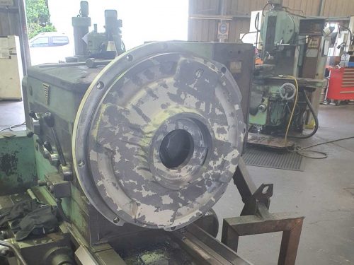
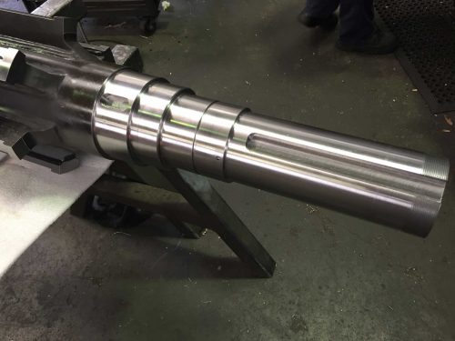
Now the couplings and shaft were one part, the dummy shaft was then placed back in the machine for final machining.

The Results:

A functional motor replacement shaft, drafted, surveyed and manufactured in record time! The replacement motor was positioned in the line so that our client could service the actual motor without affecting the operations of their customer’s business.

Want to see how we’ve assisted other clients to solve problems with their machinery? Check out our other case studies!


CASE STUDIES