REPAIRING A ROTOR SHAFT WITH SPIDER

OUR EXPERIENCE
REPAIRING A ROTOR
SHAFT WITH SPIDER

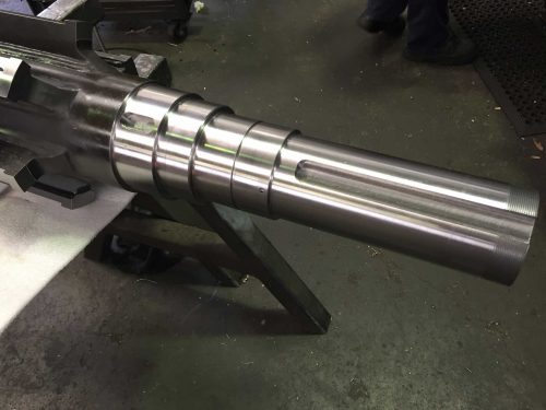
When our client came to us with a damaged electric motor, they were looking for a one-stop-shop that could do everything. As always, Prime Engineering delivered. Read on to find out how we produced a new rotor shaft that was higher in quality, more affordable and completed with an impressing lead time!

The Challenge:

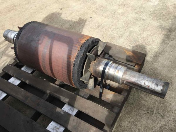
The client’s 280KW 6 Pole electric motor had damaged bearing and coupling journals. Typically, this kind of damage could be resolved with weld repair, metal spray or sleeving. However, this was not an option for this project. The client requested for us to remove the damaged shaft, supply, fabricate and machine a new shaft and fit the new shaft to the rotor.

So, we took a multi-disciplinary, creative approach…

What we did:

1

We used precision measuring equipment to measure the damaged shaft, referring to bearing literature. With this specialist information gathered, we then produced technical drawings using CAD software. The drawing went through several quality checks to ensure they were accurate.

2

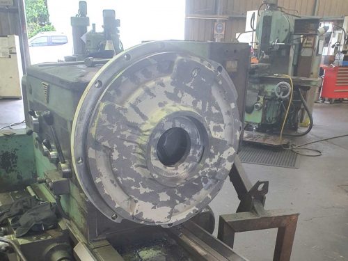
The old shaft was cut and removed from the rotor using a Band Saw and a Horizontal Borer. Quality assurance checks were completed on the bore size of the rotor to determine the new shaft size for the correct interference fit.

3

Small sample pieces of material were cut from the damaged shaft and sent to a laboratory to have a chemical analysis done. The reports came back that the closest equivalent material for the shaft was 4140 and the spokes 1045 grade plate. This determined the chemical composition of the damaged shaft. With this information, we were able to find and source equivalent materials.

4

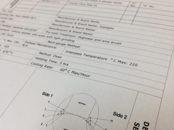
Once knowing what material we would be using, we then proceeded with producing a welding procedure. The shaft was pre-machined, and the spokes were prepped for welding. Quality assurance checks were done on the positioning of the spokes to the shaft. Once passed, the spokes were welded onto the shaft as per our drawings and the weld procedure. Stress relieving and non-destructive test were also done on the welds.

5

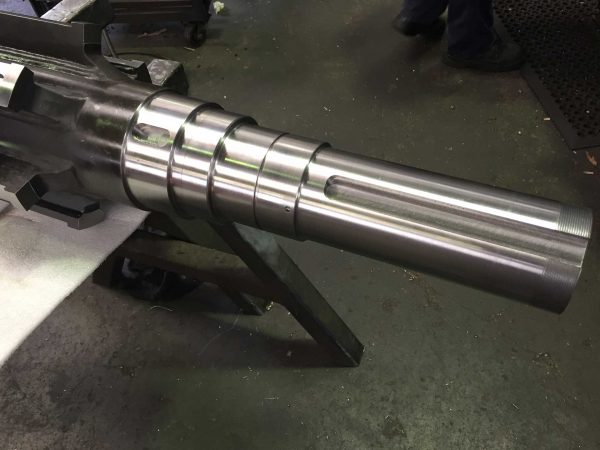
After the weld test reports had been completed and passed, the final machining of the shaft was done. The shaft went through more quality assurance checking before fitting it to the rotor.

6

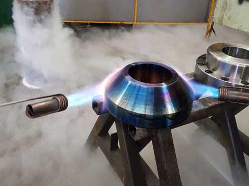
The shaft was placed in liquid nitrogen to make it shrink. LPG burners were used to heat up the rotor. The rotor warmed up to expand the bore size so the shaft could fall into the rotor. The shaft was then lowered into the rotor, and as it returned to ambient temperature, the interference fit took up and held the shaft in the rotor. One more quality assurance check is done to check the position of the shaft to the rotor and for any run outs. The final stage is to send out the assembly for dynamic balancing.

The Results:

  • CAD software drawings were made using precision measurements, so the rotor shaft was error-free and exact. We fabricated and machined the shaft according to our core business philosophy – it’s spot on, or it’s nothing at all.
  • Our client was extremely impressed with the lead time, price and quality of their new rotor shaft and its execution.


CASE STUDIES